Wave Polarization
Page 1
Wave Polarization
1 Polarization Defined
The polarization of a wave becomes very important when we consider radio communication systems, and radio wave propagation. The performance of communication systems can be strongly affected by the polarization of a wave, if it is not “matched” to the intended polarization. Along similar lines, propagation of a wave introduces potential changes to its polarization which will in turn affect communication system performance. Hence, it is important to understand how waves are polarized and the different polarization classifications.
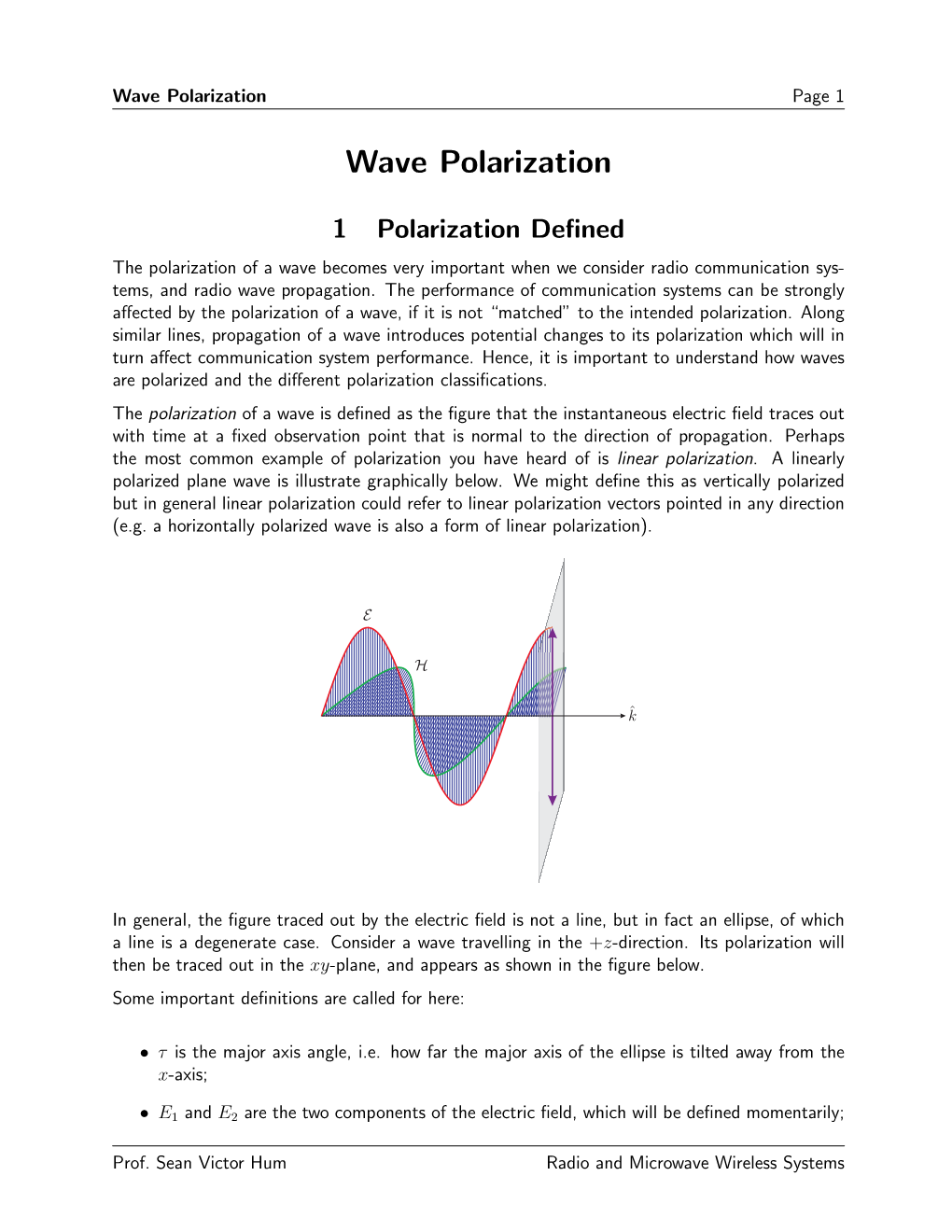
The polarization of a wave is defined as the figure that the instantaneous electric field traces out with time at a fixed observation point that is normal to the direction of propagation. Perhaps the most common example of polarization you have heard of is linear polarization. A linearly polarized plane wave is illustrate graphically below. We might define this as vertically polarized but in general linear polarization could refer to linear polarization vectors pointed in any direction
(e.g. a horizontally polarized wave is also a form of linear polarization).
In general, the figure traced out by the electric field is not a line, but in fact an ellipse, of which a line is a degenerate case. Consider a wave travelling in the +z-direction. Its polarization will then be traced out in the xy-plane, and appears as shown in the figure below.
Some important definitions are called for here:
• τ is the major axis angle, i.e. how far the major axis of the ellipse is tilted away from the x-axis;
• E1 and E2 are the two components of the electric field, which will be defined momentarily;
Prof. Sean Victor Hum
Radio and Microwave Wireless Systems Wave Polarization
Page 2
• γ is the auxilliary angle defined by tan−1 E2/E1, 0◦ ≤ γ ≤ 90◦;
• ε is the ellipticity angle defined by
OB tan ε =
, −45◦ ≤ ε ≤ 45◦
OA
.
The ratio of the major axis electric field component to that along the minor axis is called the axial ratio (AR), which is the ratio of the length of the major axis length of the polarization ellipse to the length of the minor axis length,
OA
AR = ,
1 ≤ AR ∞,
(1)
OB or cot ε = AR.
(2)
(3)
Axial ratio is related to ε through
ε = cot−1(AR).
Axial ratio is a measure of how close the polarization is to circular; if AR = 1, the polarization traced out is a circle. More specifically, a wave can be defined as being right hand circularly polarized (RHCP) or left hand circularly polarized (LHCP) if AR = 1. The “handedness” of the polarization is observed by viewing the rotation of the wave vector as it travels. If your thumb points in the direction of propagation, your fingers should curl in the direction of polarization, hence the use of “hand” in the polarization description. A sign can be arbitrarily added to the axial ratio to be more specific as to the handedness of the wave it is referring to. A positive
AR indicates a right-hand polarized wave while a negative AR indicates a left-hand polarized wave (note, not necessarily circularly-polarized). Note that the sign is simply used to indicate the handedness of the wave; it is not possible to generate a negative AR from the formulae shown above.
Coming back to the general elliptically polarized case, we can write the time varying electric field at z = 0 as follows, assuming the phase angle Ex = 0:
E(z = 0, t) = Exxˆ + Eyyˆ = E1 cos(ωt)xˆ + E2 cos(ωt + δ)yˆ.
The equivalent phasor representation is
E = E1xˆ + E2ejδyˆ.
(4)
(5)
Prof. Sean Victor Hum
Radio and Microwave Wireless Systems Wave Polarization
Page 3
Here we can see how E1 and E2 are mathematically defined: they represent the amplitudes of two orthogonally polarized electric fields. Ex and Ey represent the instantaneous value of these fields.
In general, they may be time delayed with respect to each other, such that the y-component leads the x-component by a phase angle δ.
To aid in visualizing the wave polarization, it is handy to use time snapshots. Time spacing every
T/4 or quarter-period is usually sufficient to see the evolution of the polarization.
π
2
Example: δ = , E1 = E2 produces a left-hand elliptically-polarized (LHEP) wave with an axial ratio of E2/E1, as shown in Figure 1. Note that the axial ratio is not always given by this ratio, and this formula is a special case for when the ellipse is untilted or tilted by 90◦; that is, it
π
2only holds if δ = ± .
Figure 1: Various time snapshots of an elliptically-polarized wave travelling in the +z direction.
2 Special Cases of Polarization
Linear Polarization
A wave is linearly polarized when
δ = nπ, n = 0, 1, 2, . . .
(6)
Prof. Sean Victor Hum
Radio and Microwave Wireless Systems Wave Polarization
Page 4
In this case the polarization ellipse collapse to a line, which in itself has infinite axial ratio. The angle of polarization γ depends on the amplitudes E1 and E2, as described earlier:
E2
γ = tan−1 .
(7)
E1
Note a linearly polarized wave has an axial ratio of infinity (AR → ∞).
Circular Polarization
A wave is circularly polarized when
π
δ = ± , E1 = E2.
(8)
(9)
2
More specifically, the two CP cases are
ꢀ
π
2
−
LHCP
RHCP
δ = .
π
2
In either case, AR = 1, as discussed previously.
3 Polarization State
For an arbitrary polarization case, the variables (δ, γ) completely define the state of polarization.
Alternatively, (ε, τ) can also be used to describe the state of polarization with the same detail.
To convert between any representation, you can use the following sets of formulas,
1
γ = cos−1(cos 2ε cos 2τ)
(10)
(11)
2
ꢁꢂtan 2ε sin 2τ
δ = tan−1 .
and tan 2τ = (tan 2γ) cos δ sin 2ε = (sin 2γ) sin δ.
(12)
(13)
Prof. Sean Victor Hum
Radio and Microwave Wireless Systems
Wave Polarization