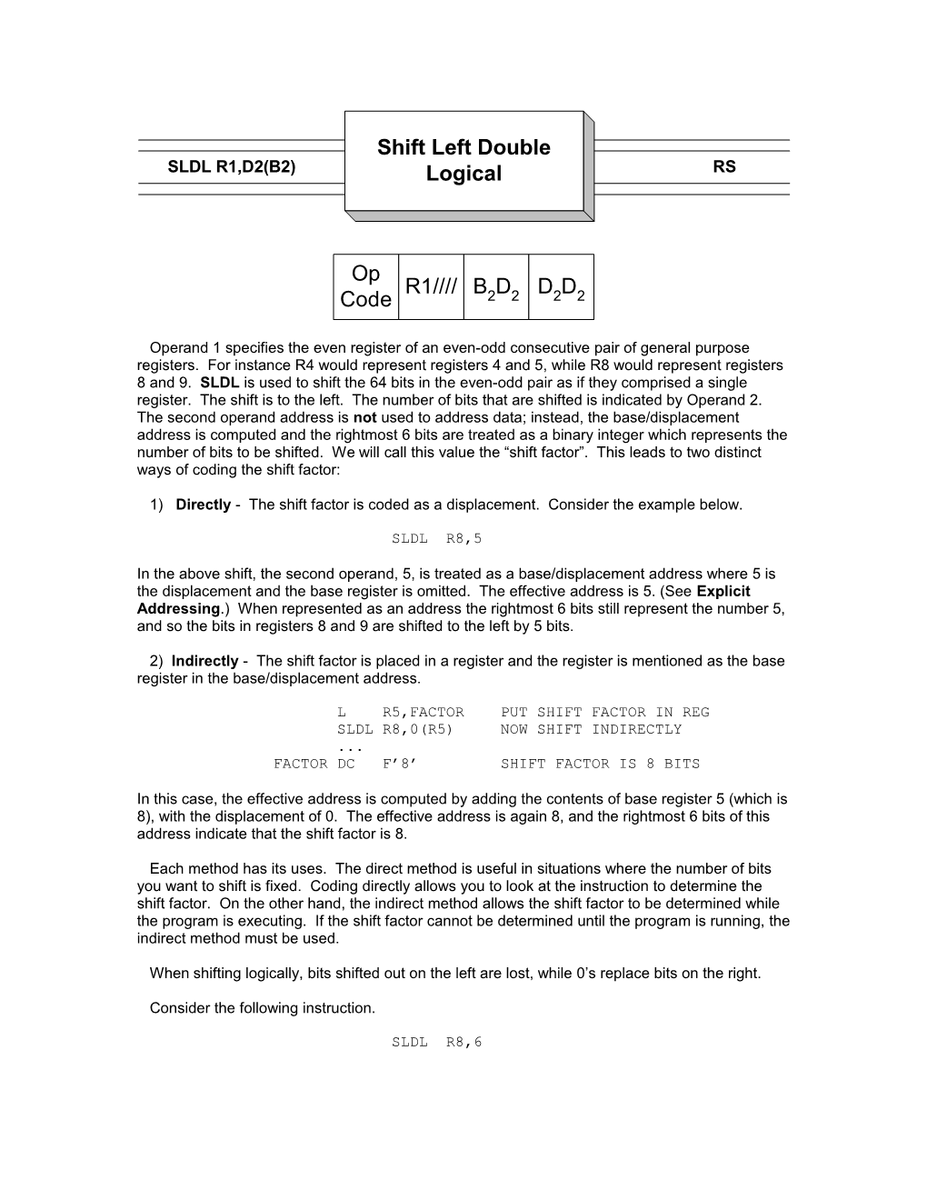
Operand 1 specifies the even register of an even-odd consecutive pair of general purpose registers. For instance R4 would represent registers 4 and 5, while R8 would represent registers 8 and 9. SLDL is used to shift the 64 bits in the even-odd pair as if they comprised a single register. The shift is to the left. The number of bits that are shifted is indicated by Operand 2. The second operand address is not used to address data; instead, the base/displacement address is computed and the rightmost 6 bits are treated as a binary integer which represents the number of bits to be shifted. We will call this value the “shift factor”. This leads to two distinct ways of coding the shift factor:
1) Directly - The shift factor is coded as a displacement. Consider the example below.
SLDL R8,5
In the above shift, the second operand, 5, is treated as a base/displacement address where 5 is the displacement and the base register is omitted. The effective address is 5. (See Explicit Addressing.) When represented as an address the rightmost 6 bits still represent the number 5, and so the bits in registers 8 and 9 are shifted to the left by 5 bits.
2) Indirectly - The shift factor is placed in a register and the register is mentioned as the base register in the base/displacement address.
L R5,FACTOR PUT SHIFT FACTOR IN REG
SLDL R8,0(R5) NOW SHIFT INDIRECTLY
...
FACTOR DC F’8’ SHIFT FACTOR IS 8 BITS
In this case, the effective address is computed by adding the contents of base register 5 (which is 8), with the displacement of 0. The effective address is again 8, and the rightmost 6 bits of this address indicate that the shift factor is 8.
Each method has its uses. The direct method is useful in situations where the number of bits you want to shift is fixed. Coding directly allows you to look at the instruction to determine the shift factor. On the other hand, the indirect method allows the shift factor to be determined while the program is executing. If the shift factor cannot be determined until the program is running, the indirect method must be used.
When shifting logically, bits shifted out on the left are lost, while 0’s replace bits on the right.
Consider the following instruction.
SLDL R8,6
This instruction represents a left shift of registers 8 and 9 using a shift factor of 6. The shift factor has been coded directly. As a result, 6 bits, 111100, are shifted out of the register on the left. Vacated bit positions on the right are replace by 0’s. This is illustrated in the diagram below.
This instruction has an RS format but the 4 low-order bits of the second byte are unused.
Some Unrelated SLDL’s
R4 = B’11110000111111111111111111111111’
R5 = B’00000000000000000000000000001111’
SLDL R4,1 R4 = B’11111111111111111111111111111110’
R5 = B’00000000000000000000000000011110’
SLDL R4,2 R4 = B’11111111111111111111111111111100’
R5 = B’00000000000000000000000000111100’
SLDL R4,31 R4 = B’10000000000000000000000000000111’
R5 = B’10000000000000000000000000000000’
SLDL R4,32 R4 = B’00000000000000000000000000001111’
R5 = B’00000000000000000000000000000000’
SLDL R4,4 R4 = B’00001111111111111111111111110000’
R5 = B’00000000000000000000000011110000’
L R9,=F’3’
SLDL R4,0(R9) R4 = B’10000111111111111111111111111000’
R5 = B’00000000000000000000000001111000’
L R3,=F’5’
SLL R4,0(R3) R4 = B’00011111111111111111111111100000’
R5 = B’00000000000000000000000111100000’