NTRODUCTION
1.1.SUSPENSION SYSTEM
Suspension is the term given to the system of springs, shock absorbers and linkages that connects a vehicle to its wheels. Suspension systems serve a dual purpose — contributing to the car's roadholding /handling and braking for good active safety and driving pleasure, and keeping vehicle occupants comfortable and reasonably well isolated from road noise, bumps, and vibrations,etc. These goals are generally at odds, so the tuning of suspensions involves finding the right compromise. It is important for the suspension to keep the road wheel in contact with the road surface as much as possible, because all the forces acting on the vehicle do so through the contact patches of the tires. The suspension also protects the vehicle itself and any cargo or luggage from damage and wear. The design of front and rear suspension of a car may be different.
1.2. SUSPENSION DESIGN CONFLICTS
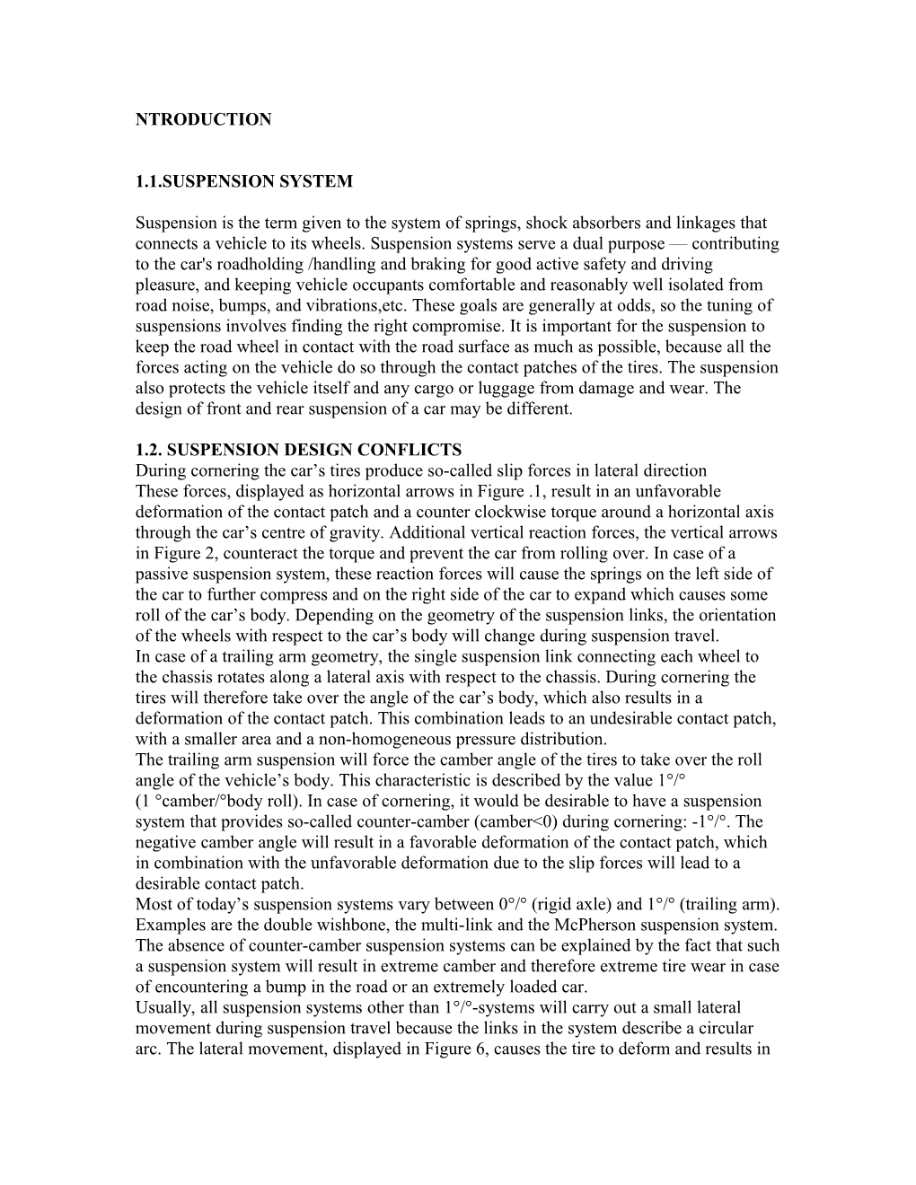
During cornering the car’s tires produce so-called slip forces in lateral direction
These forces, displayed as horizontal arrows in Figure .1, result in an unfavorable deformation of the contact patch and a counter clockwise torque around a horizontal axis through the car’s centre of gravity. Additional vertical reaction forces, the vertical arrows in Figure 2, counteract the torque and prevent the car from rolling over. In case of a passive suspension system, these reaction forces will cause the springs on the left side of the car to further compress and on the right side of the car to expand which causes some roll of the car’s body. Depending on the geometry of the suspension links, the orientation of the wheels with respect to the car’s body will change during suspension travel.
In case of a trailing arm geometry, the single suspension link connecting each wheel to the chassis rotates along a lateral axis with respect to the chassis. During cornering the tires will therefore take over the angle of the car’s body, which also results in a deformation of the contact patch. This combination leads to an undesirable contact patch, with a smaller area and a non-homogeneous pressure distribution.
The trailing arm suspension will force the camber angle of the tires to take over the roll angle of the vehicle’s body. This characteristic is described by the value 1°/°
(1 °camber/°body roll). In case of cornering, it would be desirable to have a suspension system that provides so-called counter-camber (camber<0) during cornering: -1°/°. The negative camber angle will result in a favorable deformation of the contact patch, which in combination with the unfavorable deformation due to the slip forces will lead to a desirable contact patch.
Most of today’s suspension systems vary between 0°/° (rigid axle) and 1°/° (trailing arm). Examples are the double wishbone, the multi-link and the McPherson suspension system. The absence of counter-camber suspension systems can be explained by the fact that such a suspension system will result in extreme camber and therefore extreme tire wear in case of encountering a bump in the road or an extremely loaded car.
Usually, all suspension systems other than 1°/°-systems will carry out a small lateral movement during suspension travel because the links in the system describe a circular arc. The lateral movement, displayed in Figure 6, causes the tire to deform and results in extra tire wear. This is prevented in case of 1°/°-systems like a trailing arm suspension
PROPERTIES OF SUSPENSION SYSTEM
2.1. SPRING RATE(OR SUSPENSION RATE)
The spring rate is a component in setting the vehicle's ride height or its location in the suspension stroke. Vehicles which carry heavy loads will often have heavier springs to compensate for the additional weight that would otherwise collapse a vehicle to the bottom of its travel (stroke). Heavier springs are also used in performance applications where the loading conditions experienced are more extreme.
Mathematics of the spring rate
Spring rate is a ratio used to measure how resistant a spring is to being compressed or expanded during the spring's deflection. The magnitude of the spring force increases as deflection increases according to Hooke's Law. Briefly, this can be stated as
Where,
F is the force the spring exerts
k is the spring rate of the spring.
x is the displacement from equilibrium length i.e. the length at which the spring is neither compressed or stretched.
The spring rate of a coil spring may be calculated by a simple algebraic equation or it may be measured in a spring testing machine. The spring constant k can be calculated as follows:
where d is the wire diameter, G is the spring's shear modulus (e.g., about 12,000,000 lbf/in² or 80 GPa for steel), and N is the number of wraps and D is the diameter of the coil.
2.2. WHEEL RATE
Wheel rate is the effective spring rate when measured at the wheel. This is as opposed to simply measuring the spring rate alone.Wheel rate is usually equal to or considerably less than the spring rate. Commonly, springs are mounted on control arms, swing arms or some other pivoting suspension member.
2.3. ROLL COUPLE PERCENTAGE
Roll couple percentage is the effective wheel rate, in roll, of each axle of the vehicle as a ratio of the vehicle's total roll rate. Roll couple percentage is critical in accurately balancing the handling of a vehicle. It is commonly adjusted through the use of anti-roll bars, but can also be changed through the use of different springs.
2.4. WEIGHT TRANSFER
Weight transfer during cornering, acceleration or braking is usually calculated per individual wheel and compared with the static weights for the same wheels.
The total amount of weight transfer is only affected by four factors: the distance between wheel centers the height of the center of gravity, the mass of the vehicle, and the amount of acceleration experienced.
Unsprung weight transfer-Unsprung weight transfer is calculated based on the weight of the vehicle's components that are not supported by the springs. This includes tires, wheels, brakes, spindles, half the control arm's weight and other components.
Sprung weight transfer-Sprung weight transfer is the weight transferred by only the weight of the vehicle resting on the springs, not the total vehicle weight..
2.5. JACKING FORCES
Jacking forces are the sum of the vertical force components experienced by the suspension links. The resultant force acts to lift the sprung mass if the roll center is above ground, or compress it if underground. Generally, the higher the roll center, the more jacking force is experienced.
2.6. TRAVEL
Travel is the measure of distance from the bottom of the suspension stroke to the top of the suspension stroke . Bottoming or lifting a wheel can cause serious control problems or directly cause damage. "Bottoming" can be caused by the suspension, tires, fenders, etc. running out of space to move or the body or other components of the car hitting the road.
2.7. DAMPING
Damping is the control of motion or oscillation, as seen with the use of hydraulic gates and valves in a vehicles shock absorber. This may also vary, intentionally or unintentionally. Like spring rate, the optimal damping for comfort may be less than for control.
2.8. CLAMBER CONTROL
Camber changes is due to wheel travel, body roll and suspension system deflection or compliance. In general, a tire wears and brakes best at -1 to -2° of camber from vertical. Too much camber will result in the decrease of braking performance due to a reduced contact patch size through excessive camber variation in the suspension geometry. The amount of camber change in bump is determined by the instantaneous front view swing arm (FVSA) length of the suspension geometry, or in other words, the tendency of the tire to camber inward when compressed in bump.
2.9. ROLL CENTER HEIGHT
This is important to body roll and to front to rear roll stiffness distribution. However, the roll stiffness distribution in most cars is set more by the antiroll bars than the RCH. The height of the roll center is related to the amount of jacking forces experienced.
2.10. ANTI-DIVE AND ANTI-SQUAT
Anti-dive and anti-squat are expressed in terms of percentage and refer to the front diving under braking and the rear squatting under acceleration. They can be thought of as the counterparts for braking and acceleration as jacking forces are to cornering. The main reason for the difference is due to the different design goals between front and rear suspension, whereas suspension is usually symmetrical between the left and right of the vehicle.
2.11 . ISOLATION FROM HIGH FREQUENCY SHOCK
For most purposes, the weight of the suspension components is unimportant, but at high frequencies, caused by road surface roughness, the parts isolated by rubber bushings act as a multistage filter to suppress noise and vibration better than can be done with only the tires and springs. (The springs work mainly in the vertical direction.)
2.12. AIR RESISTANCE (DRAG)
Certain modern vehicles have height adjustable suspension in order to improve aerodynamics and fuel efficiency. And modern formula cars, that have exposed wheels and suspension, typically use streamlined tubing rather than simple round tubing for their suspension arms to reduce drag..
ACTIVE SUSPENSION
During the design of a suspension system, a number of conflicting requirements has to be met. The suspension setup has to ensure a comfortable ride and good cornering characteristics at the same time. Also, optimal contact between wheels and road surface is needed in various driving conditions in order to maximize safety. Instead of a passive suspension, present in most of today’s cars, an active suspension can be used in order to better resolve the trade-off between these conflicts. However, this is generally accompanied by considerable energy consumption. An active suspension is capable of leveling the car during cornering theoretically without consuming energy. Simulations using a full-car model show that this maximizes the car’s cornering velocity. As extreme cornering may be required to remain on the road or to avoid an obstacle, implementing the active suspension system improves safety.
As the active part of the suspension takes care of realizing good cornering behaviour and of static load variations, the primary suspension springs can be tuned purely for optimizing comfort and road holding. Simulations show that the required energy for leveling the car during cornering is negligible, so it can be concluded that the active suspension system is able to economically level the car. The active suspension’s potential for improving comfort is examined using a quarter-car model in combination with the skyhook damping principle. Performing simulations with an unrestricted actuator shows that comfort can slightly be improved with little actuator action and without deteriorating road holding and suspension travel. Further improving the comfort level requires more actuator action and results in considerable degradation of road holding and suspension travel
WORKING
The major components of an active suspension system are a linear actuator, a microcontroller, and a sensor system that will allow us to monitor the displacement, velocity, and acceleration An input wave will be sent into the system, via the microcontroller, and the platform will move according to the type of wave entered. The wave entered will be asingle step, a square wave, or a sine wave with different options available for the user to control. This actuator will be controlled using a microcontroller . Thedisplay will show the maximum distance the platform moves, the maximum velocity and acceleration of the actuator, and the type of motion the it is undergoing (i.e. up or down).Sensors will permit monitoring and recording of the platform motion.
ACTIVE SUSPENSION-DESIGN
CONTROLLER DESIGN
In this section, a controller will be designed which regulates the adjustable arm’s angle and therefore the force produced by the active suspension. The control of the suspension system takes place in two stages. In the first stage a performance improvement controller determines the force that has to be produced by the active suspension for leveling the car, comfort improvement, wheel load variation reduction,
suspension travel reduction or a combination of these improvements. The required force functions as input for the actuator controller.In the second stage an actuator controller makes sure that the required force is produced as precise as possible. The actuator is capable of producing a force within certain limits. Therefore, a saturation filter first warrants that the force stays within these limits. Using the mathematical model, this limited required force is converted to an angle at which theactuator actually produces this force. This angle is called the reference angle . Hereafter, the actuator controller drives the adjustable arm, via a moment applied by an electric actuator, to the reference angle using a PD-controller with a correction for the estimated disturbance. This disturbance is caused by the reaction moment and can be predicted by the mathematical model. The actuator controller components are visualized
FUNCTIONS OF ACTIVE SUSPENSION
Improves driver control, safety and stability, with or without a load .
Eliminates sway and reduces roll on corners
Reduces axle wrap
Maximum safety
Absorbs load, rather than resisting it, thereby ensuring a much more comfortable ride
Eliminates the need for fitting extra blades which harden the ride
Better handling and control in windy and rough road conditions
Minimize wear on tires, shocks, shackles and leaf springs
CONCLUSION
Usually the suspension consists of passive force elements which are designed to optimize the trade-off between ride comfort, suspension travel and wheel load variations. Also, the geometry design of the suspension links is a trade off between optimal orientation of the wheels in case of bumps in the road or during cornering. Furthermore, the springs should be stiff enough to avoid exaggerate body roll or pitch during cornering, accelerating and braking. Modern suspension systems provide possibilities for optimizing the trade-offs, but will never be able to eliminate the conflicts. Moreover, they are complex and space consuming. The additional elements of an active suspension system are able to produce forces when required and therefore the trade-off between ride comfort, suspension travel and wheel load variations can be better resolved. Furthermore, an active suspension system can be used in order to eliminate body roll during cornering. As a result, the complicated and space consuming suspension links can be replaced with a compact and simple trailing arm suspension. Also, static load variations can be taken care of by adjusting the stiffness of the suspension. It can be adjusted to the driving situation and to individualize the handling characteristics and comfort level of the vehicle.
NTRODUCTION 1.1.SUSPENSION SYSTEM Suspension Is the Term Given to the System of Springs