TECHNICAL PAPER
LEAD ACID BATTERY working – LIFETIME STUDY
Valve Regulated Lead Acid (VRLA) Batteries
Overview
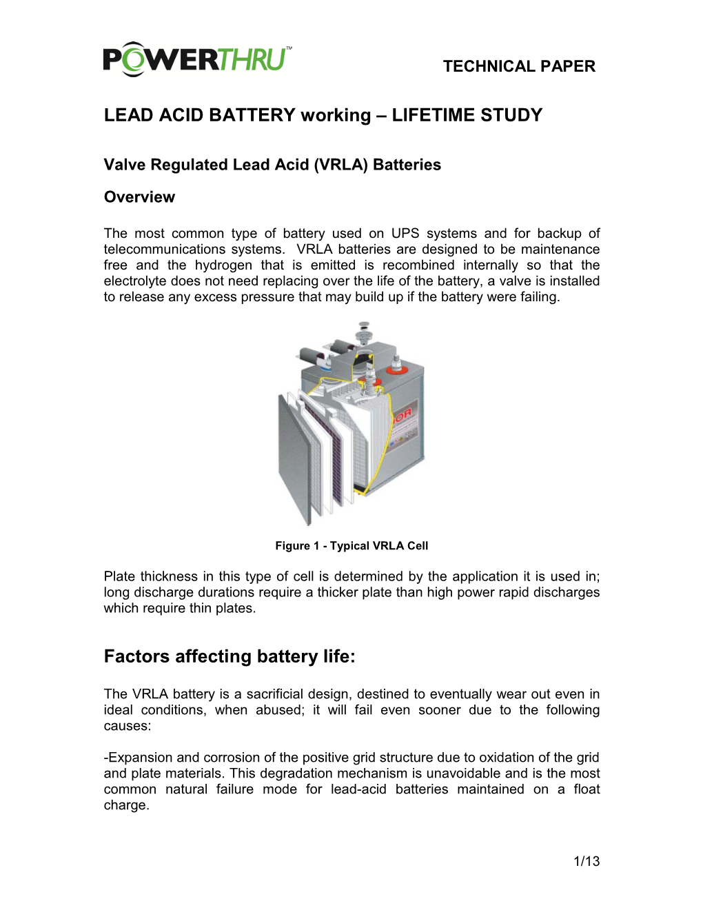
The most common type of battery used on UPS systems and for backup of telecommunications systems. VRLA batteries are designed to be maintenance free and the hydrogen that is emitted is recombined internally so that the electrolyte does not need replacing over the life of the battery, a valve is installed to release any excess pressure that may build up if the battery were failing.
Figure 1 - Typical VRLA Cell
Plate thickness in this type of cell is determined by the application it is used in; long discharge durations require a thicker plate than high power rapid discharges which require thin plates.
Factors affecting battery life:
The VRLA battery is a sacrificial design, destined to eventually wear out even in ideal conditions, when abused; it will fail even sooner due to the following causes:
-Expansion and corrosion of the positive grid structure due to oxidation of the grid and plate materials. This degradation mechanism is unavoidable and is the most common natural failure mode for lead-acid batteries maintained on a float charge.
1/13 TECHNICAL PAPER
-Loss of active material from the positive plate.
-Loss of capacity due to physical changes in the active material of the positive plate.
- Design life. VRLA batteries are typically available with a design life ranging from 3 to 10 years. Longer life batteries generally cost more due to increased plate thickness or more costly materials.
- Temperature. Elevated temperatures reduce battery life. An increase of 8.3°C
(15°F) can reduce lead-acid battery life by 50% or more.
- Cycle service. Discharge cycles reduce life. Lead calcium batteries can be rated for as few as 50 deep discharge cycles. Many lifetime calculations for UPS systems are based on 1 to 2 Deep discharges per year. (Deep discharge is anything greater than 25% capacity)
Figure 2 - Lifetime Curves (Cycles)
2/13 TECHNICAL PAPER
- Overcharging. Excessively high float voltages cause a higher positive plate corrosion rate. Overcharging also causes excessive gassing. Recharging after a discharge must be controlled to 10% of the discharge current to prevent damage to the cells.
- Undercharging. A low float voltage reduces capacity because of self-discharge.
Undercharging can also result in sulfation, which can damage the plates.
- DC ripple current. Excessive DC ripple current might contribute to battery aging.
VRLA batteries are considered to be extremely susceptible to ripple current since it can lead to cell heating and will accelerate the degradation of cells which are at risk from thermal runaway.
- Manufacturing variations. Lot-to-lot processing variations can shorten battery life because the float voltage of each individual cell is not controlled and it is unlikely that they will all be at their optimum value.
- Improper storage. Storing wet cells beyond the manufacturer’s recommended duration promotes sulfation, and decreases cell capacity and life.
- Misapplications. Batteries are commonly designed for a specific use. If the battery is not designed for a given application, it might not meet its life or performance expectations.
End of Life
If properly designed, built, and maintained, a battery can provide many years of reliable service. A new battery might not initially provide 100% capacity. The capacity typically improves over the first few years of service, reaches a peak, and declines until the battery reaches its end of life. A reduction to 80% of the rated capacity is usually defined as the end of life for a lead-acid battery.
Below 80%, the rate of battery deterioration accelerates, and it is more prone to sudden failure resulting from a mechanical shock (such as a seismic event) or a high discharge rate. Note that even under ideal conditions, a battery is expected to eventually wear out.
3/13 TECHNICAL PAPER
Battery Failure Modes in Detail
- Temperature Effects:
Anticipated battery life is specified by the manufacturer for batteries installed in an environment at or near the reference temperature of 25°C (77°F). Above this temperature, battery life is reduced. The chief aging mechanism is accelerated corrosion of the positive plates, grid structure, and strap, which increases exponentially as a function of temperature.
- Rule of Thumb:
A general rule of thumb for a vented lead-acid battery is that the battery life is halved for every 15°F (8.3°C) above 77°F (25°C). Thus, a battery rated for 5 years of operation under ideal conditions at 77°F (25°C) might only last 2.5 years at 95°F (35°C).
Figure 3 - Lifetime Curves (Temperature)
- Discharge Cycles
Battery failure rates, as defined by a loss of capacity and the corrosion of the positive plates, increase with the number of discharge cycles and the depth of discharge. Lead-acid batteries having lead calcium grid structures are particularly susceptible to aging due to repeated cycling. A deep discharge cycle is defined as any discharge over 80% of the rated capacity. Most manufacturers provide warranties based on the number of discharge cycles
4/13 TECHNICAL PAPER
- Overcharging:
Occasional charging at higher voltages, such as an equalizing charge, can benefit the battery by removing plate sulfation and refreshing the plates.
However, habitual overcharging damages the plates. The chart below highlights how charging at the wrong float voltage can drastically increase corrosion.
Figure 4 - Lifetime Curves (Float Voltage)
- Undercharging:
Batteries lose capacity because of self-discharge if they are consistently undercharged. An undercharge condition is indicated by a low specific gravity, low cell voltage, or lighter color on the plates. An undercharged battery might not be at full capacity and can become permanently damaged from sulfation.
Chronic undercharging results in a harmful buildup of lead sulfate on the plates, called sulfation. Lead sulfate formed as a result of undercharging is inherently different in structure from lead sulfate formed during normal cell discharge. The lead sulfate formed during normal discharge has a very fine crystalline structure that is easily broken down by charging current. The lead sulfate crystals formed as a result of undercharging continue to grow and eventually reach a size that cannot be easily broken down by charge current. Additionally, the lead sulfate crystals physically occupy more space than the original active material. An excessive buildup of lead sulfate can make the plates warp or buckle.
5/13 TECHNICAL PAPER
- Overdischarge:
Hydration occurs in a lead-acid battery that is overdischarged and not promptly recharged, or a battery that remains in a discharged condition for an extended time (such as might occur during long-term storage). Hydration results when the lead and lead compounds of the plates dissolve in the water of a discharged cell and form lead hydrate, which is deposited on the separators. When the cell is recharged, multiple internal short circuits occur between the positive and negative plates. Once hydration is evident, the cell is permanently damaged.
Hydration is not visible in VRLA cells because the containers are opaque.
The chart below illustrates actual cell voltage taken from an aging UPS string:
Figure 5 - Float Voltage Variation
The benefits of maintaining the float voltage at an optimum level for the batteries are well understood however, it is no always achievable in the field, for example, replacement cells for failed cells will be of a different age than the remaining cells. This will contribute to float voltage variations, but cannot be avoided because replacement cells are required. Usually, replacing the entire battery just because a few cells failed is not acceptable from a budget perspective. As more cells are replaced each year, the chances of having equal float characteristics across the battery become less and less, the chart. shows an extreme case of float voltage variations; notice that some cells are below the desired charging voltage while other cells are overcharged to the point of extreme gassing, none of the cells are operated at the manufacturer’s recommended float voltage of 2.25 V per cell.
6/13 TECHNICAL PAPER
The chart below outlines the reason for failures in the most common forms of batteries:
Figure 6 - Causes of Failure
Many VRLA batteries are installed throughout the world and the industry is beginning to acknowledge that a 20 year VRLA battery life is unlikely to realize. Recent industry experience indicates that a 4 to 7 year VRLA battery life is more likely, regardless of cell size or warranty claims. In one study of almost 25,000 VRLA cells from 9 different manufacturers, the failure rates ranged from 27% to 86%, depending on the manufacturer. These cells were only 3 to 7 years old. The average failure rate was 64% for the entire tested population. This study concluded that the failures were generic and appeared to be independent of size or manufacturer over a range from 25 to 1,000 ampere-hours.
A European study of over 1,000 installations, of various system voltages and cell capacities, containing about 35,000 cells concluded that VRLA batteries require replacement after 5 to 8 years of operation. The shorter lifetime (5 years) was associated with batteries operating at 110 V or higher system voltages. The longer lifetime (up to 8 years) was applicable to better quality batteries and those of lower system voltages. Absorbed Glass Matt-type cells demonstrated a higher failure rate than did gel-type cells. No single or systematic factor was determined to cause this short lifetime. Representatives of a major battery company recently provided an update regarding VRLA cells’ expected life. Four different VRLA cells were tested, including three different AGM types and one gel-type. It was concluded that 20-year class AGM cells actually have an expected life of 5 years at 25°C (77°F), dropping to about 3 years at 32°C (90°F).
7/13 TECHNICAL PAPER
In summary, VRLA batteries can have a shorter than-advertised life and some manufacturers have acknowledged this limitation. With each generation, VRLA batteries will likely continue to improve. However, their greatest strengths that make them so popular for use are also their greatest weaknesses in terms of the user’s ability to identify cell failures.
Coup-de-Fouet Detailed Description
The initial voltage drop observed during discharge occurs because of two effects.
First, the loss of the battery charger float voltage causes the battery voltage to fall to its open circuit voltage, or lower; the amount of voltage drop depends on the discharge rate. Second, an additional temporary voltage dip might be also observed in which the battery voltage initially falls to some minimum level, followed by a slow recovery to a slightly higher voltage during the first few minutes of discharge. This initial voltage dip is referred to as the coup-de-fouet and its effect is primarily observed on stationary lead-acid batteries that have been maintained on a long-term float charge.
Figure 7 - Coup de Fouet - Typical Cell Voltage Dip at Beginning of Discharge
The coup-de-fouet primarily occurs with batteries on long term float for the following reason:
- The float charge process maintains the positive plates in a nearly fully charged condition, in which the active material is all lead dioxide, PbO2, with very little lead sulfate, PbSO4, present under ideal conditions. During discharge, lead dioxide is converted to lead sulfate. However, the chemical reaction is better facilitated when a lead dioxide molecule is located adjacent to a lead sulfate molecule. In other words, the chemical reaction process improves in efficiency as lead sulfatesites are generated. During the initial moments of discharge, the chemical reaction is slightly less efficient, with the result that the voltage can dip to a lower than expected value and slowly recover from this voltage dip during the first few minutes of discharge as these lead sulfate sites are created.
8/13 TECHNICAL PAPER
The coup-de-fouet effect can limit the high-rate discharge capability of a particular cell design. Some users have been caught by surprise during the first minute of a high-rate discharge. In the 1980s, some UPS users experienced a high rate discharge on their system in which battery voltage would fall below the low-voltage cutout of the UPS during the first minute of discharge. After resetting the low-voltage trip, the UPS would perform normally without again actuating its low-voltage trip. After further investigation, it was discovered that the coup-defouet dip during the first discharge had fallen low enough to trip the low-voltage trip, in so doing, enough lead sulfate sites had been established that the subsequent battery discharge at the same rate would not experience as low of a dip. Some battery manufacturers were forced to de-rate their cell ratings to account for this effect.
Quantifying Battery Lifetime
Estimating battery lifetime is an entire topic in itself however, It is clear that battery life is affected by many parameters and it is possible to control most of these with careful design. One of the comments which has been banded about is that “Batteries don’t fail, they are murdered!” , by this they mean that batteries are slowly cooked and overcharged due to the fact that they need a temperature controlled environment and careful setting of the charge parameters and a small number of discharges to even approach their design life. Batteries are considered to be dead when their capacity drops to 80% of their original design.
From the complete list of factors which can affect battery life it is clear that a number of contributors stand out:
1. Temperature – The ambient temperature of the cells is a major factor in the lifetime of any battery system. The chart below defines the reduction in lifetime through operating at elevated temperatures. This also has an effect on the ideal float voltage which needs to be controlled based on the ambient temperature to prevent over or under charging which can also lead to a reduction in lifetime.
Figure 8 Lifetime Chart (Temperature)
9/13 TECHNICAL PAPER
2. Age – Cells will degrade with age, VRLA batteries are much more susceptible to age because they trade off lower maintenance for lifetime.
Factors which occur with age include corrosion of the plates, drying out and sludge build up from flaking which can short out plates.
3. Number and Depth of Cycles, just using batteries caused them to age.
This can be quantified and is shown in the chart below. This chart clearly shows that if the number of discharges and the depth of these discharges can be kept to a minimum then the life of the battery will be extended.
Figure 9 - Battery Lifetime (Cycles – Measured Data)
This study was based on a good quality VRLA cell however, some cells are sold with a guarantee of only 100 full discharges over their lifetime and as such, following the same characteristics, the total number of cycles at 20% depth of discharge would be reduced to only 260 cycles.
4. Additional factors which are specific to large banks of cells typically used in UPS systems are overcharging due to a single cell shorting with leads to overcharging of the other cells. Loss of a string due to one cell failing and effectively taking the others out of service. Corrosion due to the corrosive environment the batteries are operating in.
Relating Battery Life to UPS Systems:
The biggest challenge for the operators of UPS systems is to ensure that the life of their batteries is extended as much as possible. They can do this by operating the batteries in a temperature controlled environment and this will offer a significant increase in lifetime so long as the number of discharges is relatively small. Further gains can be made by installing a battery monitoring system and performing regular maintenance to change out older cells which may be failing and damaging to good cells within the string.
10/13 TECHNICAL PAPER
If we relate all this information to the real world, using a power quality study that was performed across the United States, we can expect to receive on average 1
(10 in the worst locations) complete outage every month and 90 (2700+ in worst areas) short transients and or voltage sag/transient events which will lead to a short discharge from the batteries. In the average case we would see the VRLA batteries needing to be changed out approximately every 8 years, so in this case the batteries would have already been changed out due to other forms of degradation. However, if we look at the worst case we see that the batteries would need to be changed at 2 year intervals well before their design life (Data based on a VRLA battery guaranteed for 1400 cycles). There are also additional factors such as the quality of the batteries installed, if we were to look at the same cases from a battery guaranteed for 100 complete discharges we see that in the average case we would need to change out the batteries every year.
So What is killing Batteries?
The data has shown us that so long as we control the temperature in our battery room, perform regular maintenance on our cells and install a quality battery in the first place, we should see our batteries last the design life of 5 years (VRLA) 15 years (Flooded), so why do some battery banks need to be changed out so often even when these sensible measures are taken?
The answer is also provided by the power quality report performed across the United States, which states “50 % or more of the recorded power quality events were generated within the building” this is a significant finding and also has implications on the design of UPS systems.
The number of external grid disturbances on the average system totals approx
90 per month of which half will lead to some sort of discharge from the batteries and 1 will lead to a full discharge. We have shown already that this number of discharges is not significant enough to affect their lifetime because the depth of discharge is relatively short. However, many industrial applications for UPS system and industries such as Hospitals and Broadcasting stations are regularly switching on loads approaching the full capacity of the UPS system, this has different effects depending upon the type of UPS employed, typically an expensive UPS with an IGBT front end will compensate very quickly for the sag in DC link voltage and the batteries are unlikely to see the disturbance, older designs and cheaper UPS systems typically have an SCR front end which will sag the voltage every time a large load is applied to the point whereby the batteries discharge to support the load.
11/13 TECHNICAL PAPER
So let’s do the Math:
A large load in a hospital such as imaging equipment is switched on 10 times a day and each time the DC bus voltage within the UPS dips low enough to call on the batteries to support the load.
That is 70 discharges a week (3640 discharges a year + 45 grid side disturbances), even if our batteries are well maintained and in an air conditioned environment, they are unlikely to last more than 3 years!!
How can the flywheel help?
Flywheel energy storage systems offer a cleaver alternative to batteries in a number of ways, their performance is unaffected by elevated temperatures, their life is not adversely affect by numerous cycles and they are essentially maintenance free.
LEAD ACID BATTERY Working – LIFETIME STUDY