Creating a Realistic Teddy Bear in Maya—Part 1
1. Setting Up Reference Images
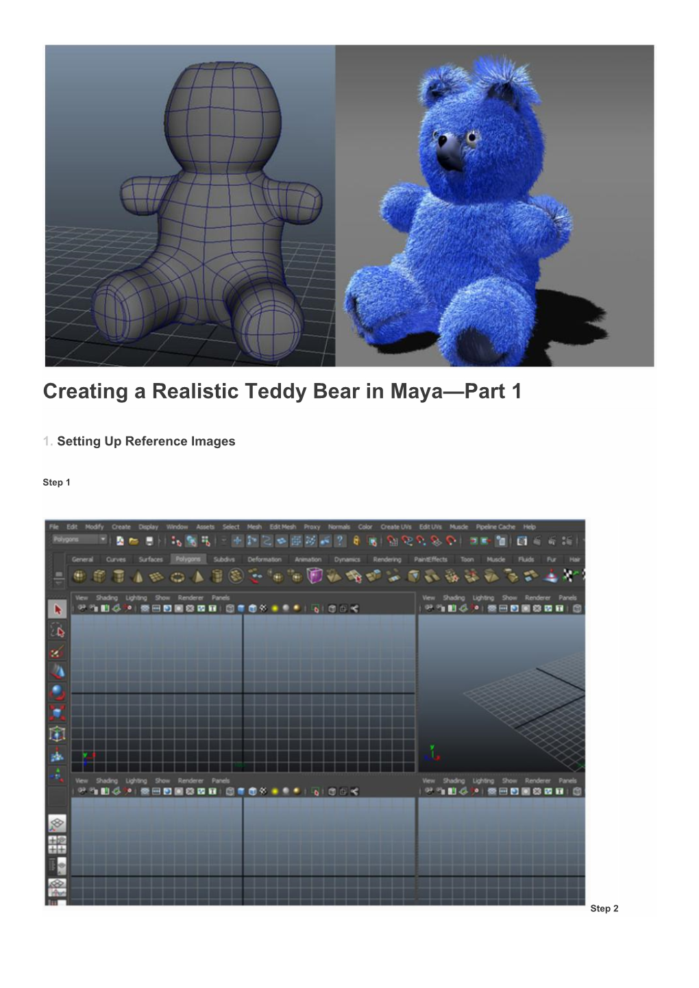
Step 1
Step 2 Load the reference images of the teddy bear in the front and left views. To do that, click on the View menu in the panel view menu and then click on Image
Plane and then click on the Import Image option.
Step 3
Go to the reference file location and load the front profile image of the teddy bear in the front view. Step 4
Following the same way, load the side image profile in the side view as well. Step 5
In the front view panel menu bar, go to View Select Camera command. Step 6
With the camera selected in the front view, click on image plane shape attribute tab. Step 7
Under the Placement Extras rollout menu, set the value of Image Center Y axis to 14.450. Step 8
Following the same way, jump in the side view and set the values of Image Center X axis to -15.00 and Y axis to 14.450. Step 9
In the perspective view, set the value of Image Center Z axis to -15.00 to create a small gap between the images. Step 10
Turn on Looking Through Camera radio button to hide the reference images in the perspective view. 2. Modelling Teddy Bear's Body
Step 1
In the perspective view, create a cylinder poly primitive. Step 2
With the cylinder selected, press Ctrl-A key. It opens the Channel Editor. In the Inputs parameter, set the values of Subdivisions
Axis to 8 and Subdivisions Height to 4. Step 3
With the cylinder selected, do a secondary-click on it and choose the Vertex command—alternatively you can press the F9 key.
This action will bring you into the vertex component mode. Then, with the Move tool selected or by pressing the W key on the keyboard to activate the Move tool, adjust the vertices of the cylinder according to the image reference and as shown in the following image. Step 4
Being in the perspective view, press F11 key for face selection mode and then select half part of the cylinder. Go to Edit Delete command to delete the selected faces. Step 5
With the half polygon mesh selected, go to the Edit menu and click on Duplicate Special option box. Step 6
In the Duplicate Special Option window, turn on Instance radio button. Keep the Scale X value as -1.00. Click on Duplicate Special button to duplicate the selected half polygon mesh. Step 7
In the front view, go to Shading menu in the panel menu bar and turn on X Ray option to make the polygon object see-through. Step 8
Jump in the vertex mode and adjust the vertices of the polygon according to the reference image. Step 9
Following the same way, modify the vertices of the cylinder in the side view as well. Step 10
Press F10 key to jump in the edge selection mode. Select the upper and bottom edges and then delete them. 3. Modelling Teddy Bear's Leg
Step 1
To start with leg modelling, create a cylinder polygon primitive with Subdivision Axis as 8 and Subdivision Height as 4 and place it under thigh area as shown in the following image. Step 2
Rotate the cylinder mesh as shown in the following image. Step 3
Select and delete the triangular edges of the leg mesh. Step 4
Delete the cap faces of the opposite side of the leg mesh. Step 5
With the cap faces of the cylinder selected, apply Extrude command to extrude the faces a bit. Step 6
Scale down the extruded faces a little bit. Step 7
Extrude the selected faces twice more and adjust them as shown in the following image. Step 8
You can see the mesh in smooth display mode by pressing 3 on the keyboard. Step 9
Go to Edit Mesh Insert Edge Loop Tool. Step 10
Insert an edge loop as shown in the following image. 4. Adjoining Torso and Leg
Step 1
With the torso and leg polygon meshes selected, go to Mesh Combine tool to attach them together. Step 2
To merge these two meshes together, you need to have same number of border vertices in both meshes. With a vertex of the body mesh selected (where you want to connect the leg), go to Edit Mesh Chamfer Vertex command. Step 3
The chamfered vertex looks like this. Step 4
Select and delete the chamfered face. Step 5
You need to have the same amount of border vertices as you have in the leg. Step 6
Go to Edit Mesh Interactive Split Tool. Step 7
With the help of Interactive Split Tool, insert several edge loops to get eight border vertices as identical to the leg border vertices. Step 8
With the parallel and corresponding vertices of both torso and leg selected, go to Edit Mesh Mergecommand to weld them together. Step 9
To repeat the process, just press G key. Step 10
The merged mesh looks like this. Step 11
Go to Edit menu and apply Duplicate Special command to make a duplicate mirrored part of the body on the other side. Step 12
Adjust the vertices of the mesh according to the reference images of the model. Step 13
If you see the model in the side view, you will notice the leg mesh is not as thick as drawn in the model sheet. So you need to adjust the vertices to match it up with the reference image. Step 14
With all vertices of the leg selected, scale them up. Step 15
Adjust the vertices in the side view also. Step 16
In this way the torso and legs of the teddy bear are completed. 5. Modelling Teddy Bear's Hand
Step 1
To begin hand modelling, jump in the side view. Step 2
Create a cylinder primitive and put it around the hand reference in the viewport. Step 3
With the cylinder selected, go to Channel Editor and change the values of Subdivisions Axis to 8 and Subdivisions Height to 4. Step 4
Press F10 key to get in the edge selection mode. Select and the delete the triangular edges of the mesh. Step 5
Jump in the side view and arrange the hand polygon mesh according to the reference images. Step 6
Press F11 key to jump in the face selection mode. Select and delete the cap faces of the opposite side of the hand mesh. Step 7
To merge hand with the body, you need to have same number of border vertices in both meshes. With a vertex of the body mesh selected (where you want to connect the hand), go to Edit Mesh Chamfer Vertexcommand. Step 8
Select and delete the chamfered face. Step 9
With the torso and hand polygon meshes selected, go to Mesh Combine tool to attach them together. Step 10
You need to have the same amount of border vertices in the torso border as you have in the leg. Step 11
Go to Edit Mesh Interactive Split Tool and start splitting the polygons as shown in the following image. Step 12
With the parallel and corresponding vertices of both torso and hand selected, go to Edit Mesh Mergecommand to weld them together. Step 13
Insert an edge loop around the arm area as shown in the following image. Step 14
The so far completed model looks like this. 6. Modelling Teddy Bear's Head
Step 1
Create a new cylinder primitive with Subdivisions Axis as 8 and Subdivisions Height as 4. Step 2
Jump in the front view and place the cylinder around the head area as shown in the reference image. Step 3
With the head mesh selected and X-ray mode turned on, press F9 key for vertex selection mode and then adjust the vertices according to the reference image. Step 4
With the body mesh and head mesh selected, go to Mesh Combine command to attach these meshes together. Step 5
In this way the base modelling of the teddy bear is completed.
Creating a Realistic Teddy Bear in Maya—Part 1