TL 2.20
Issue 2
February 2010
CARRYING OUT A FUEL FLOW CHECK TO A PUMPED FUEL SYSTEM
One of the most common causes of engine failures on homebuilt aircraft is inadequate fuel flow leading to fuel starvation or vapour lock.
Many different factors can cause inadequate fuel flow, including:
•Fuel pipes or filters partially blocked by debris, kinks, or being pinched.
•Use of pipes, fittings, etc, of inadequate internal bore size.
•Fuel cocks that are partially closed when the knob indicates fully open.
•Blocked fuel tank vents.
•Malfunctioning or insufficiently powerful pump.
•Excessive fuel ‘lift height’ required.
NORMALLY ASPIRATED ENGINES
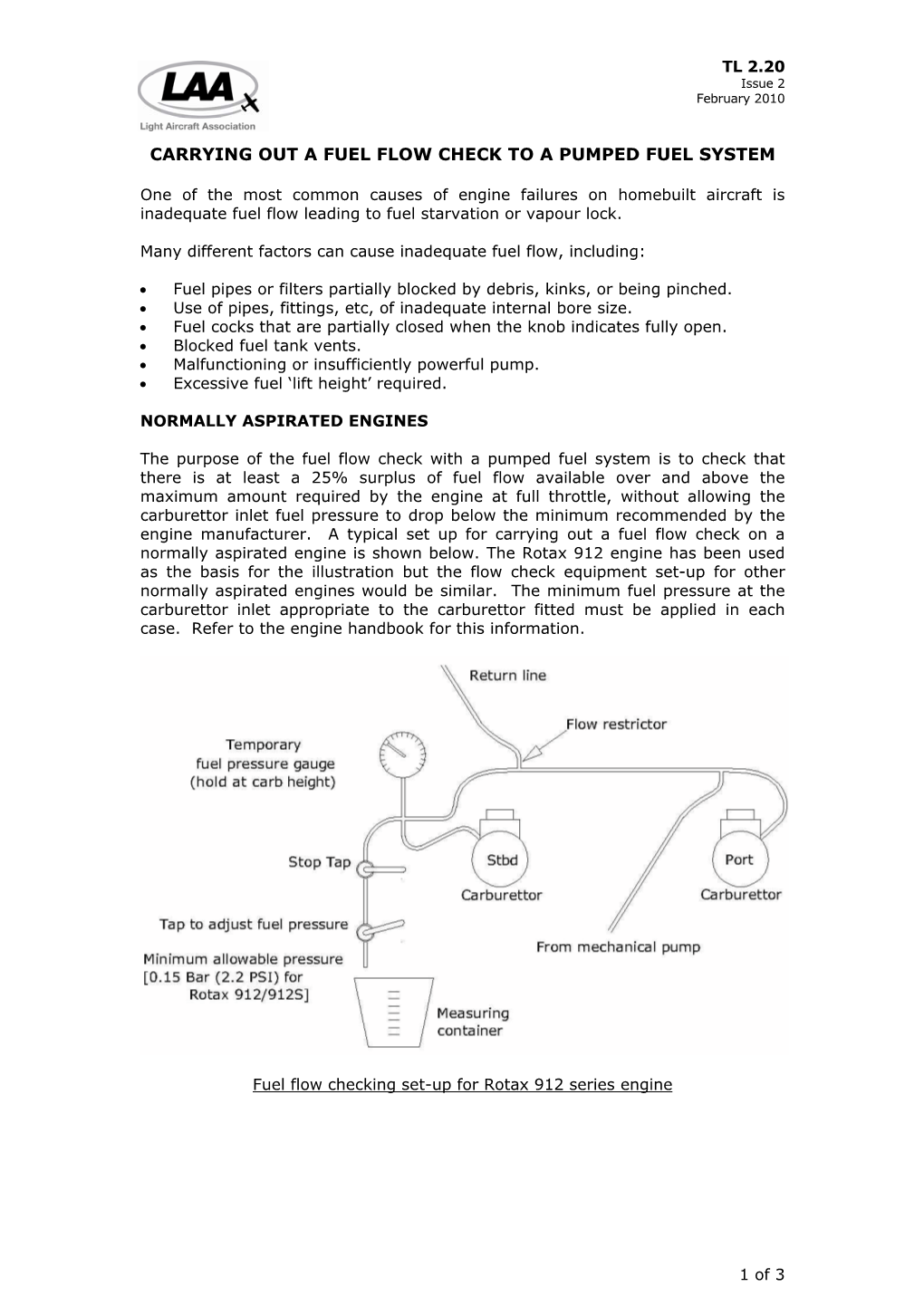
The purpose of the fuel flow check with a pumped fuel system is to check that there is at least a 25% surplus of fuel flow available over and above the maximum amount required by the engine at full throttle, without allowing the carburettor inlet fuel pressure to drop below the minimum recommended by the engine manufacturer. A typical set up for carrying out a fuel flow check on a normally aspirated engine is shown below. The Rotax 912 engine has been used as the basis for the illustration but the flow check equipment set-up for other normally aspirated engines would be similar. The minimum fuel pressure at the carburettor inlet appropriate to the carburettor fitted must be applied in each case. Refer to the engine handbook for this information.
Fuel flow checking set-up for Rotax 912 series engine
1 of 3 TL 2.20
Issue 2
February 2010
CARRYING OUT A FUEL FLOW CHECK TO A PUMPED FUEL SYSTEM
Electric back-up pump
Once the flow checking equipment is installed, if an electric pump is included in the fuel system it is best to check this pump first. It is important to set the required fuel pressure before starting to collect the fuel to be measured. Set the electric pump running and, with the stop tap fully open adjust the other tap until the carburettor inlet fuel pressure has fallen to the minimum figure permitted for the carburettor type. Close the stop tap, empty the measuring container and start timing the next time you open the stop tap. Monitor and adjust the fuel pressure as necessary and re-start the test if the pressure is not correct. Ideally, allow at least 2 litres to be collected as the more fuel collected the more accurate the result. The measured flow represents the full capacity of the electric fuel pump and system.
Repeat the test for all tank outlets available and record the results using the Fuel
Flow Inspection Checks form LAA/IC-FF.
To calculate the fuel flow, in litres per hour use the formula: litres collected x 3600 seconds
MEASURED FLOW WITH THE ELECTRIC PUMP FROM EACH TANK OUTLET
MUST EXCEED 125% OF MAXIMUM ENGINE FUEL-FLOW REQUIRED.
Engine driven pump
When conducting a fuel flow check of the engine driven pump, the engine will be running at full throttle. Therefore the aircraft must be securely chocked and preferably tied down. Prior to start-up, the temporary bleed-off line must be led to a position of safety, away from the whirling propeller. Ensure that somebody competent is seated in the cockpit to operate switches, monitor temperatures and pressures, etc. Agree hand signals with each other for actions such as ‘Full throttle’, ‘Idle’ and ‘Shut-down’ before engine start. Safety is paramount and, for aircraft with larger, more powerful engines, carrying out this procedure may be considered to be unacceptably hazardous. LAA, therefore, does not consider that a fuel flow check of the mechanical fuel pump is mandatory.
With the engine running at full power, open the stop tap fully and adjust the other tap to set the carburettor inlet pressure and note the time of the measured fuel run as described above. The bleed-off flow in this case represents the excess capacity of the fuel pump and system. Because the fuel collected is going to be a lot less than with the electric pump test and it is not desirable to run the engine at full throttle for extended periods, it is acceptable to collect significantly less than 2 litres, but care is required in the timing and measuring of what is collected to get an accurate result.
Repeat the test for all tank outlets available and record the results using the Fuel
Flow Inspection Checks form LAA/IC-FF.
Where an electric back-up pump is in series with the mechanical pump, it is recommended to carry out a further fuel flow test with both pumps running. Flow rate results that are less than with only a single pump operating could identify a fault in the electric pump.
MEASURED FLOW WITH THE ENGINE DRIVEN PUMP FROM EACH TANK
OUTLET MUST EXCEED 25% OF MAXIMUM ENGINE FUEL-FLOW REQUIRED.
If the measured flow is less than required, investigate the fuel system for defects as listed above, then re-test.
2 of 3 TL 2.20
Issue 2
February 2010
CARRYING OUT A FUEL FLOW CHECK TO A PUMPED FUEL SYSTEM
ROTAX 914 TURBO-CHARGED ENGINE
The set up for carrying out a fuel flow check on the Rotax 914 turbo-charged engine is shown below. Because this engine uses two electrical fuel pumps and there is no mechanical pump, flow checks can be carried out without running the engine. Rather than adjusting the fuel system pressure directly by restricting flow with the test equipment as with normally aspirated engines, the manifold pressure sensing part of the fuel pressure regulator is adjusted by air pressure to result in the correct fuel pressure. See the diagram of the test set-up.
To set the required fuel pressure before starting to collect the fuel to be measured, using a small hand pump such as a mountain bike fork pump with a pressure gauge fitted, adjust the fuel pressure regulator’s manifold pressure sensing port to 0.5 bar. With the fuel outlet hose positioned into a measuring container, set one of the electric pumps running and adjust the regulator air pressure as necessary. With everything set up correctly, switch off the pump, empty the measuring container and start timing the next time you switch on the pump.
Monitor and adjust the air pressure as necessary and re-start the test if the pressure is not correct. Ideally, allow at least 2 litres to be collected as the more fuel collected the more accurate the result. The fuel flow represents the full capacity of the electric fuel pump and system. Carry out another test with only the second pump running and then again with both pumps running.
Record the results using the Fuel Flow Inspection Checks form LAA/IC-FF.
To calculate the fuel flow, in litres per hour use the formula: litres collected x 3600 seconds
MEASURED FLOW WITH EACH COMBINATION OF ELECTRIC PUMP AND TANK
OUTLET MUST EXCEED 125% OF MAXIMUM ENGINE FUEL-FLOW REQUIRED.
If the measured flow is less than required, investigate the fuel system for defects as listed above, then re-test.
Fuel flow checking set-up for Rotax 914 turbocharged engine
3 of 3
Carrying out a Fuel Flow Check to a Pumped Fuel System